Avionics and Electrical Overview
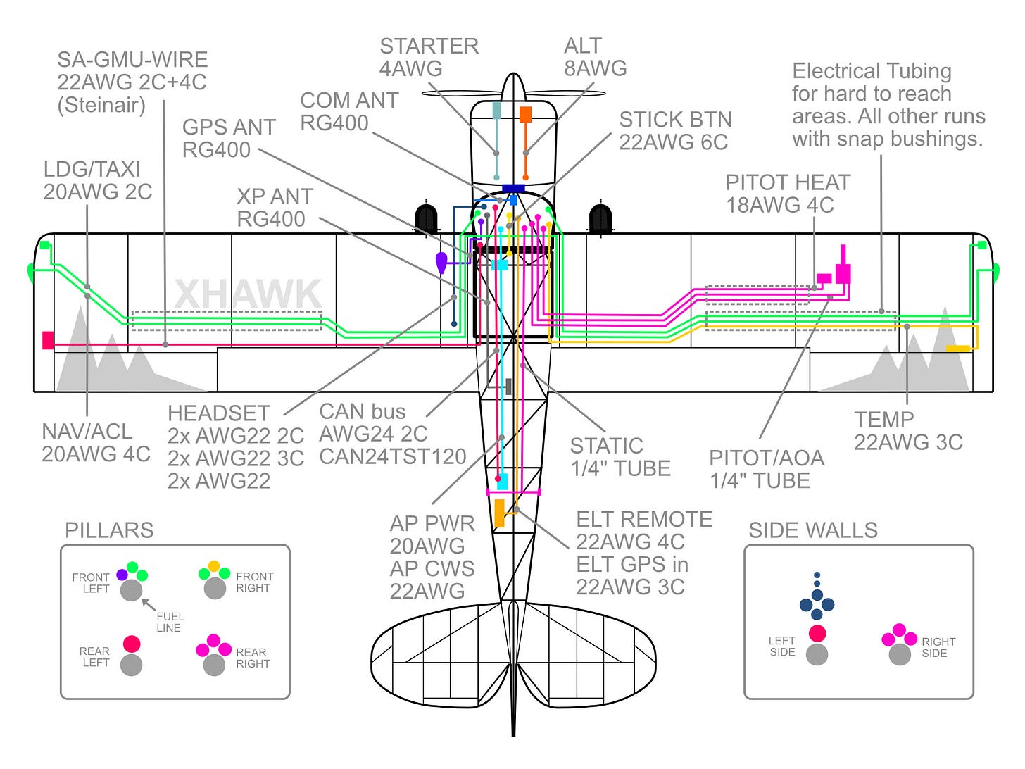
System overview of avionics sensor, actuators and electrical wiring.
The avionics and electrical system depends a lot on the intended kind of flying. This can vary quite a bit for a Bearhawk because of its wide speed envelope. On the low speed side it’s a stick and rudder airplane for low and slow visual flying. Minimal electrical components and avionics are necessary for this.
On the high speed end a Bearhawk is a decent cross country machine capable of flying long legs of 8h with standard fuel tanks and up to 14h with an auxiliary fuel bladder. This kind of flying calls for more advanced avionics and electrical systems.
Part of the fun is exploring new places. The XHawk, therefore, is built to also fly far. This means it will have a reliable GPS source (SBAS, WAAS), ADHRS, and Autopilot.
All these components need to be placed in the airframe with wires (electrical) and tubing (pitot-static) connecting them. A lot of conflicting objectives need to be sorted out. For example ADHRS need to be aligned with major airplane axes, aerials often need ground planes, line of sight, and separation from other antennae. The magnetometer needs as much separation from ferromagnetic and electro-magnetically active components.
Additionally weight and aerodynamics are always critical. Many best practices from other fields are prohibitive because of weight or drag considerations. Aerials are very hard to place and using as few external ones as possible is advisable. The XHawk also has the additional objective to be easy to cover. This means it does not have any protruding antennae at the top.
Most components are connected by wire, the pitot-static system is connected by tubing. Running all these lines under the floor boards is fairly easy.
Wire routing from the the wings to the instrument panel is easiest along the front pillars. To keep the bulk small the magnetometer wire and the pitot/AoA tubes run down the rear pillars. From there, they are routed along the respective side walls forward to avoid interference with any control cables.
The routing inside the wing is an area of conflicting objectives. Cable channels are most flexible but cause a weight penalty. Running through the rips with snap bushings is light but fairly inflexible for re-running any lines.
The XHawk uses a combination of cable channels snap bushings, and wire bundles mounted with Adele clamps. Cable channels run part of the wing where fixing or reinstalling snap bushing would be very difficult. The parts of the wing that can be reached from the wing tip or the tank bay relies on snap bushings.
Avionics Components
Also see → Instrument Panel
Part of placing these systems is following the manufacturer’s requirements. This means that some of the layout is dependent on the specific components. The XHawk layout is designed around the following items.
PFD/EIS - Garmin “G3X” GSU 460
Sensor LRU - Garmin GSU 25C
Magnetometer - Garmin GMU 11
Temp Sensor - Garmin GTP 59
Pitot/AoA - Garmin GAP 26 (heated, regulated)
Engine LRU - Garmin GEA 24
VHF Com - Trig TY-91
VHF Antenna - Rami AV-17
Transponder/ADS-B - Garmin GTX 45R
Transponder/ADS-B Antenna - Rami AV-74
WAAS GPS Source: GPS 20A
AP Controller: GMC 507
GPS Antenna: Garmin GA 35
ELT - ACK-04
Autopilot Servo - Garmin GSA 28
Fuel Flow Transducer - FT90 Gold Cube
Static Port - ACS 10-00250
CAN bus Routing
CAN bus is the main Garmin G3X standard for data exchange. It is a daisy-chained data bus where so-called LRUs (Garmin terminology) talk on the same two wires (CAN bus Hi/Low twisted pair). This requires a bit of planning on how to route the data wire between LRUs. The LRUs require a common power ground (different from shield ground) that are all connected to the same point. Unlike the data pair, the ground wires are connected in a star topology along with the device power. The XHawk uses the following CAN bus data routing:
Termination - GMU 11 - (Panel LRUs) - GSA 28 - GSA 28 - Termination
The panel LRUs are located in the panel or behind it and can be connected in any order: GSU 460, GSU 25C, GEA 24, GTX 45R, GPS 20A, GMC 507
RS232 Serial Data
Serial RS232 is the other data bus format next to CAN bus (unless you install legacy and third party devices). It is often used as a redundant backup for CAN bus but also to pipe in various data sources into LRUs.
Garmin instrument data backup: GSU 25C - GSU 460
Garmin instrument data backup: GEA 24 - GSU 460
Radio frequency loading: TY-91 - GSU 460
Barometric source: GSU 25C - GTX 45R
ADS-B GPS Source: GPS 20A - GTX 45R
UI integration: GSU 460 - GTX 45R
ELT GPS source: ACK-04 - GPS 20A (or GSU460)
Electrical Components
Battery - EarthX ETX-900-VNT (ETX-900 if on the outside)
Alternator - B & C L-40
Starter (with YO-360-A1A) - SKyTec XLT
NAV/ACL Lights - Whelen Blaze
Taxi/Landing Lights - Baja S1 flush
Stick - Tosten CS-4


