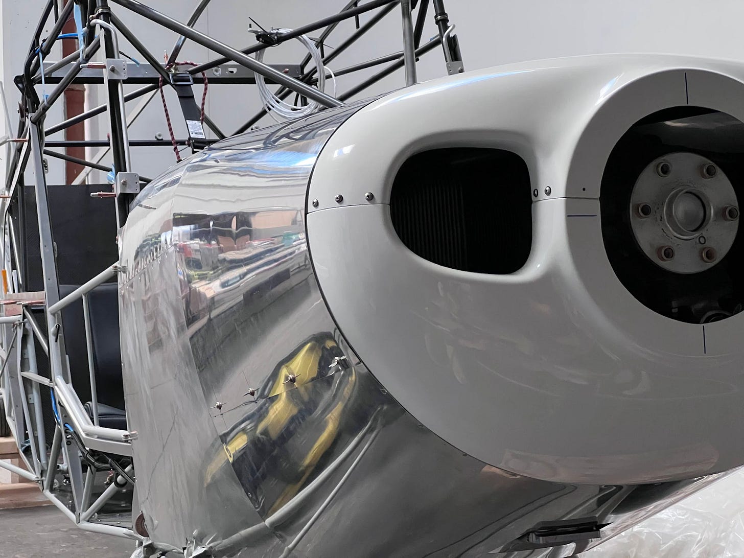
Cowling
Building the engine enclosure
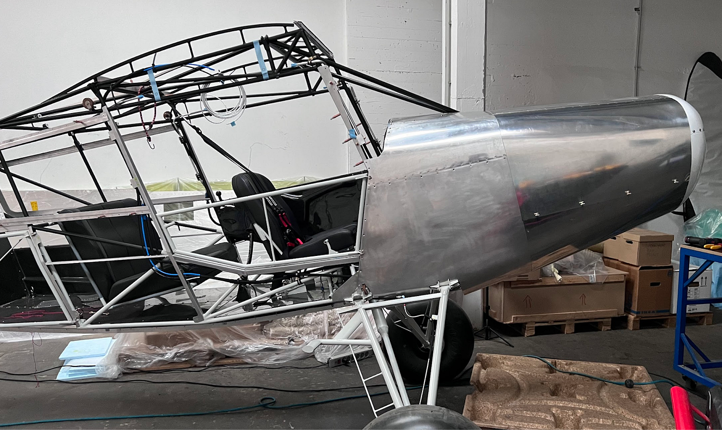
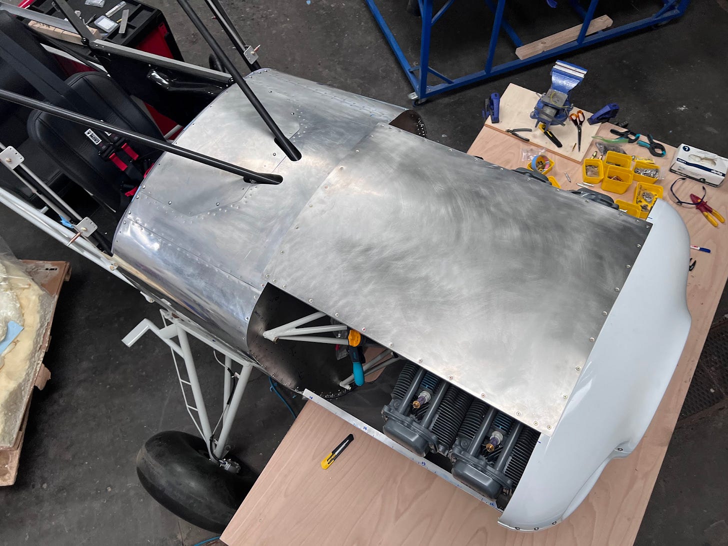
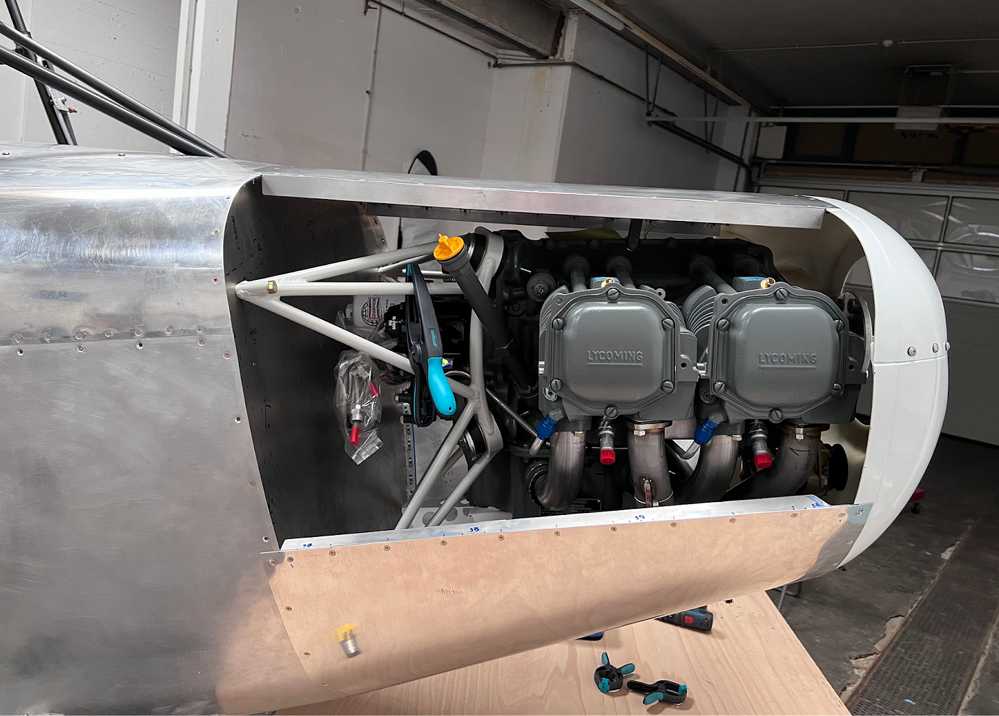
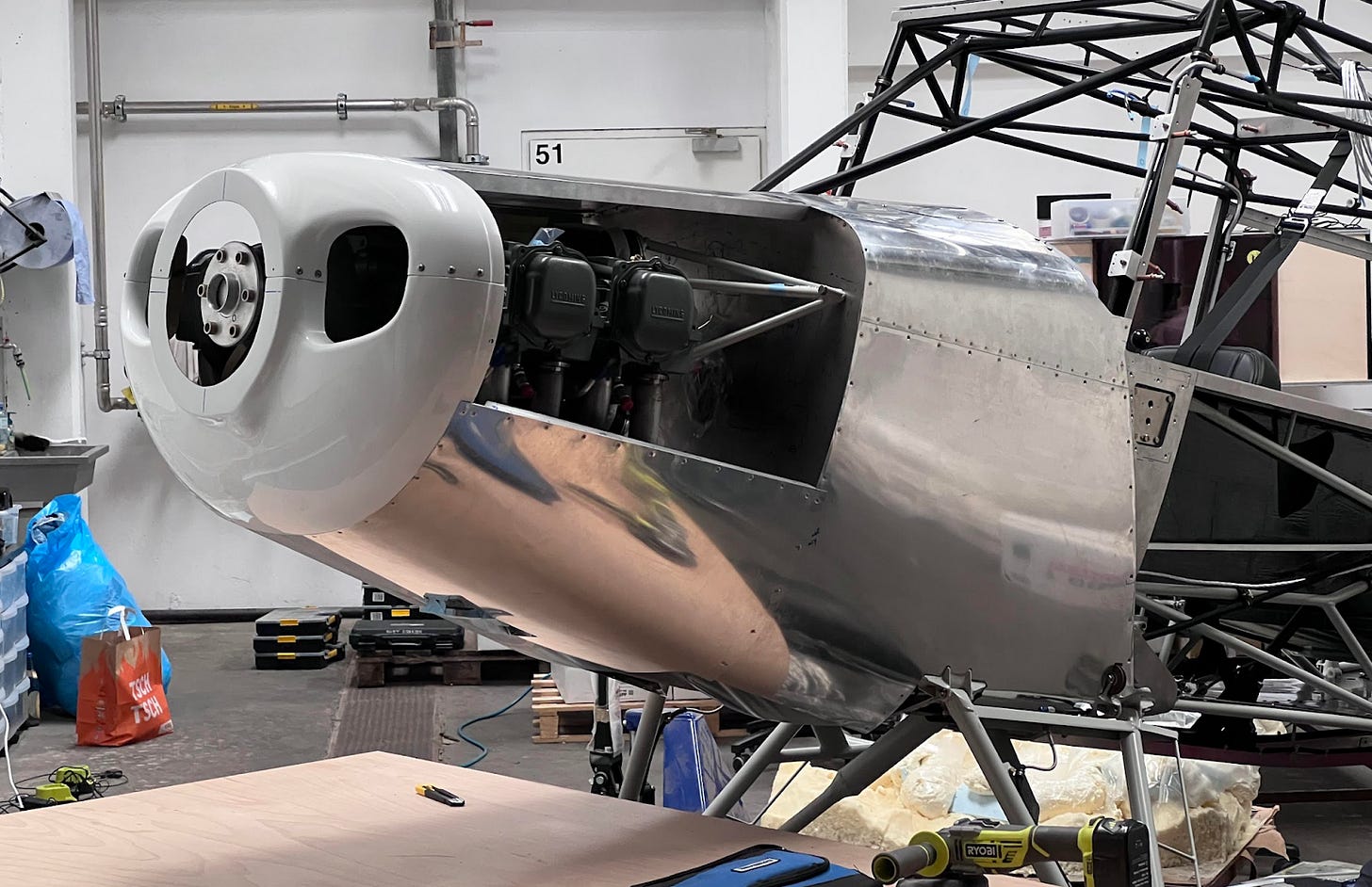
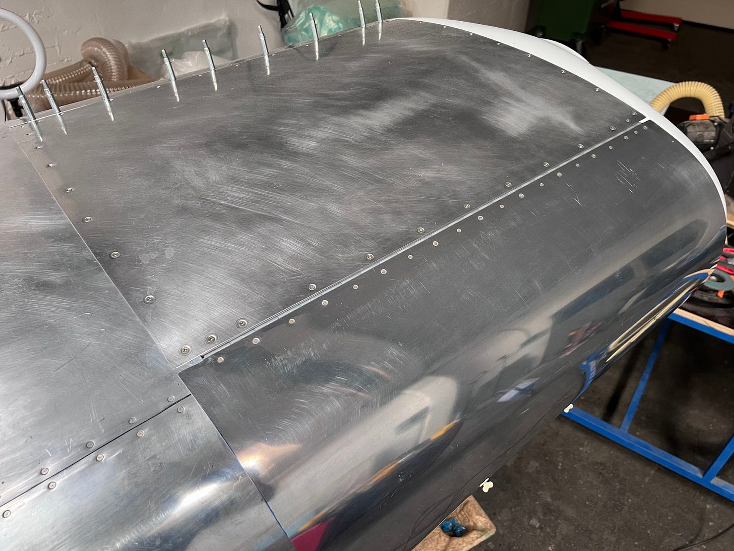
The cowling adds a lot of body to the airplane. I already feel it piercing through the air. Unlike Legos these parts will not stay on for long. Building an airplane involves a lot of disassembling and reassembling. The upside is this allows for some contemplation on how to optimize for easy maintenance. The entire cowl and boot cowl can be removed (all but the skin under the windshield).
Nose Bowl Position
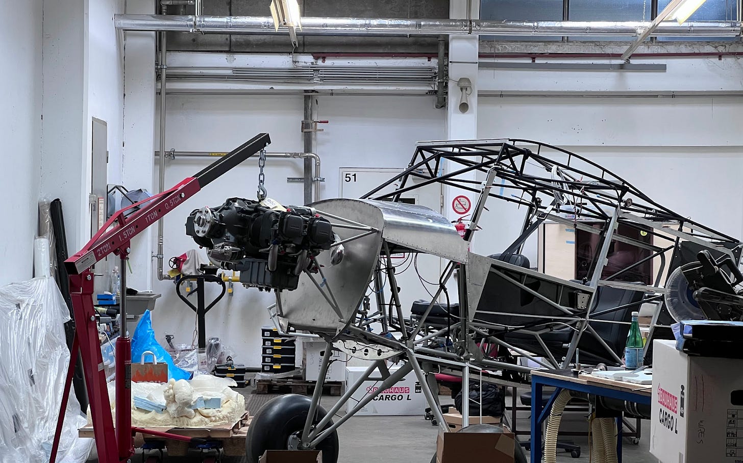
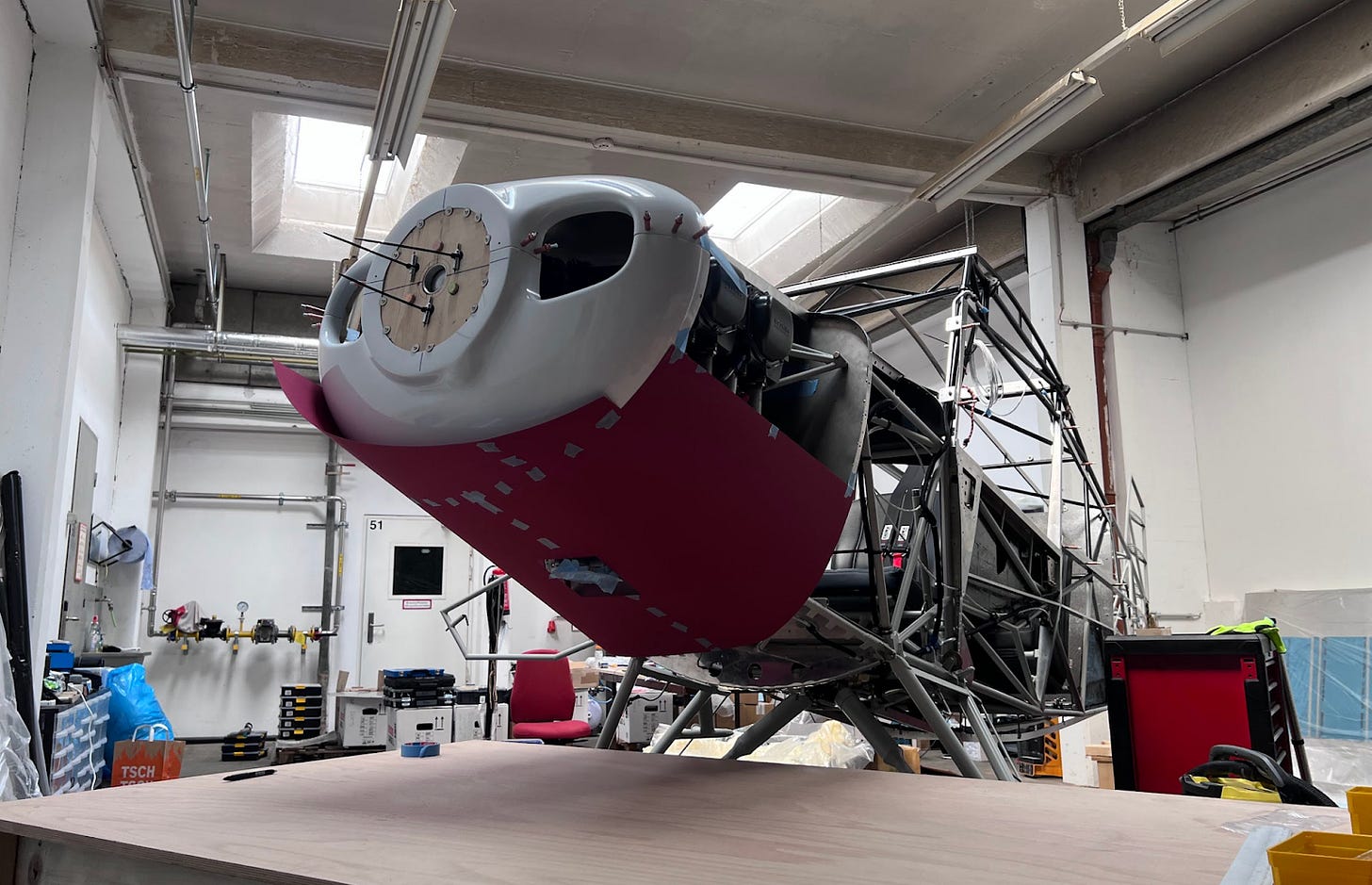
The cowl is the fuselage skin between the firewall and the spinner. It is structurally attached to the firewall flange and built in such a way that the nose bowl registers correctly with the aft edge of the spinner. This means the engine, prop and spinner have to be in place to get started.
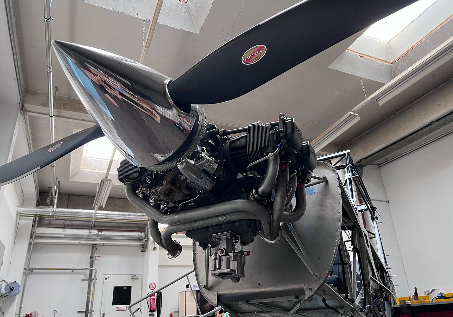
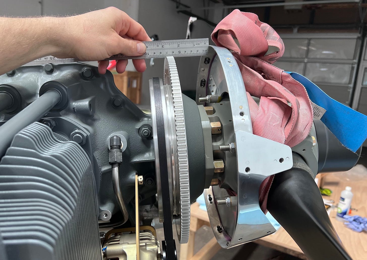
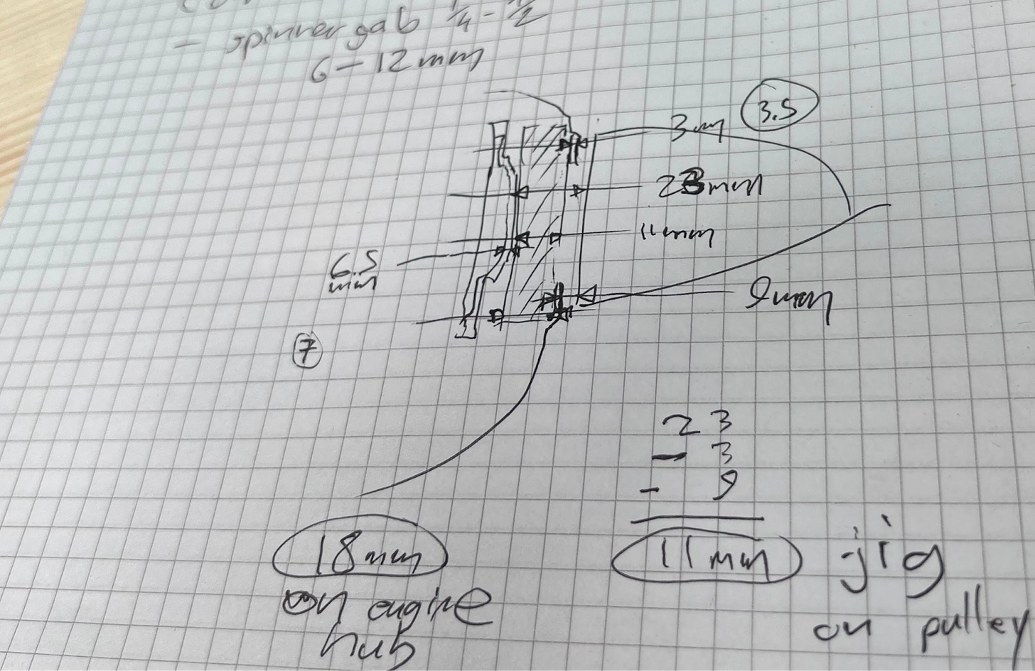
First I determined the spinner position and then positioned the nose bowl 9mm (something between 1/4 to 1/2") behind it. Apart from engine and propeller types this positioning is dependent on the following factors:
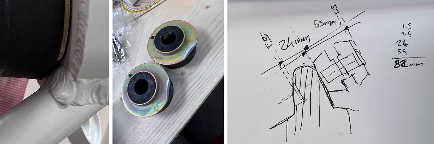
Engine mount - specifically how it is mounted to the frame. In the XHawk build I pinched the firewall with the mounting bolts. I also had to add washers between the firewall and the frame to clear some protruding welds.
Rubber dampers - The dimensions of these dampers determine the distance of the engine to the firewall. I also had to slightly modify them to assure they do not sit on a protruding weld bead.
Spinner positioning - There is a gap between the prop blades and the spinner that can be adjusted with spacers. Any adjustment here affects the pos of the spinner aft edge (lots of info in Hartzell manual).
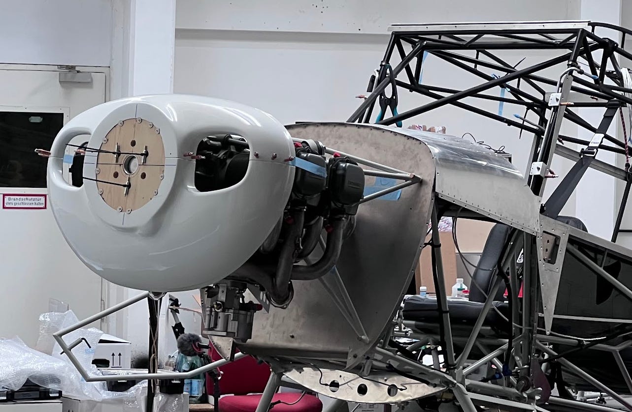
The next step is to mount the nose bowl to the engine crankshaft flange but spaced at the correct distance while making sure it is concentric and axially aligned. In my case a piece of plywood worked well (planed to the correct thickness). I used the flywheel as a template, attached it to the crankshaft flange, and mounted the nose bowl to it. To mount the nose bowl to the plywood I used screws and large washers along the inner edge of the circular opening. This made precise positioning easy.
Structural Supports
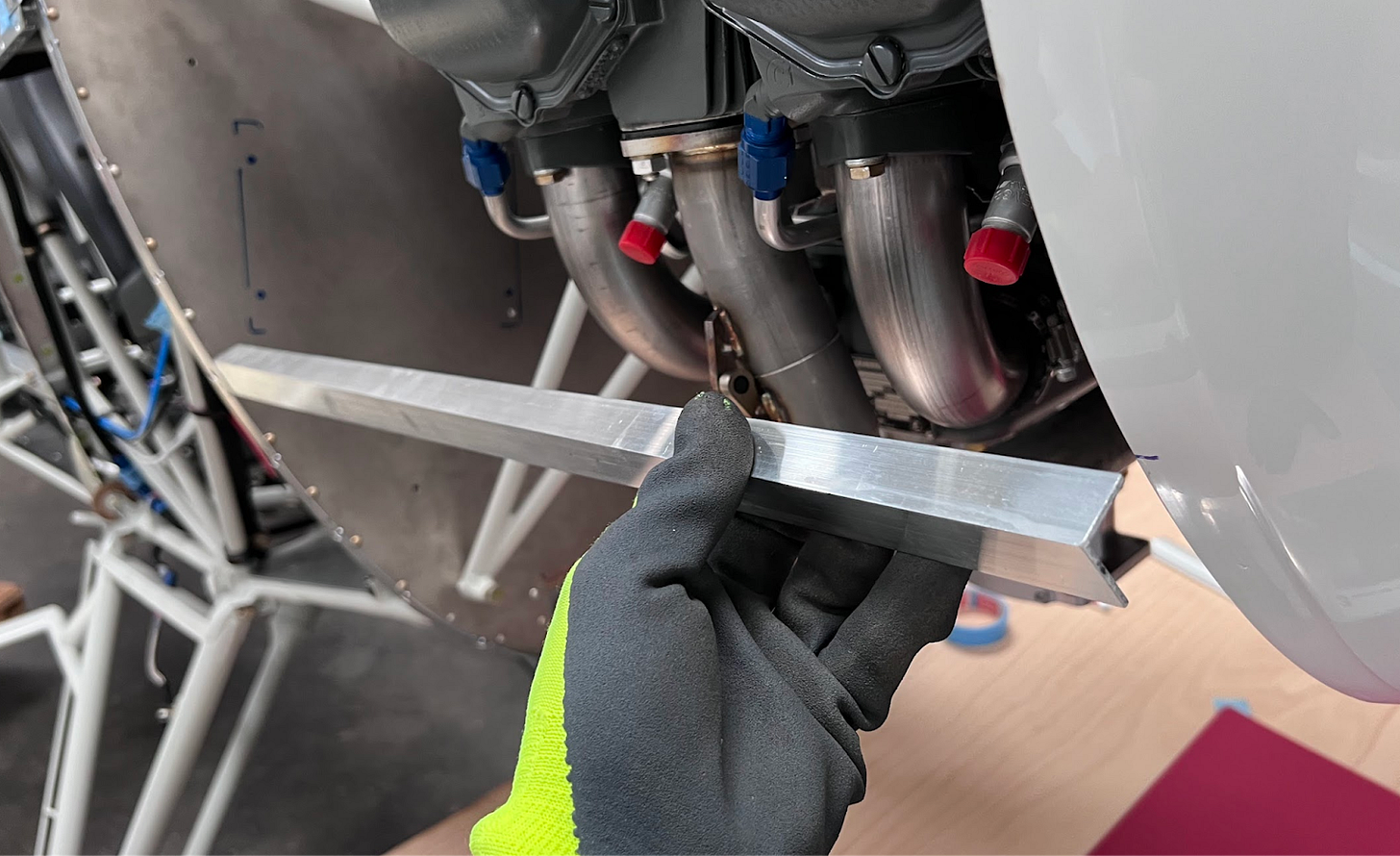
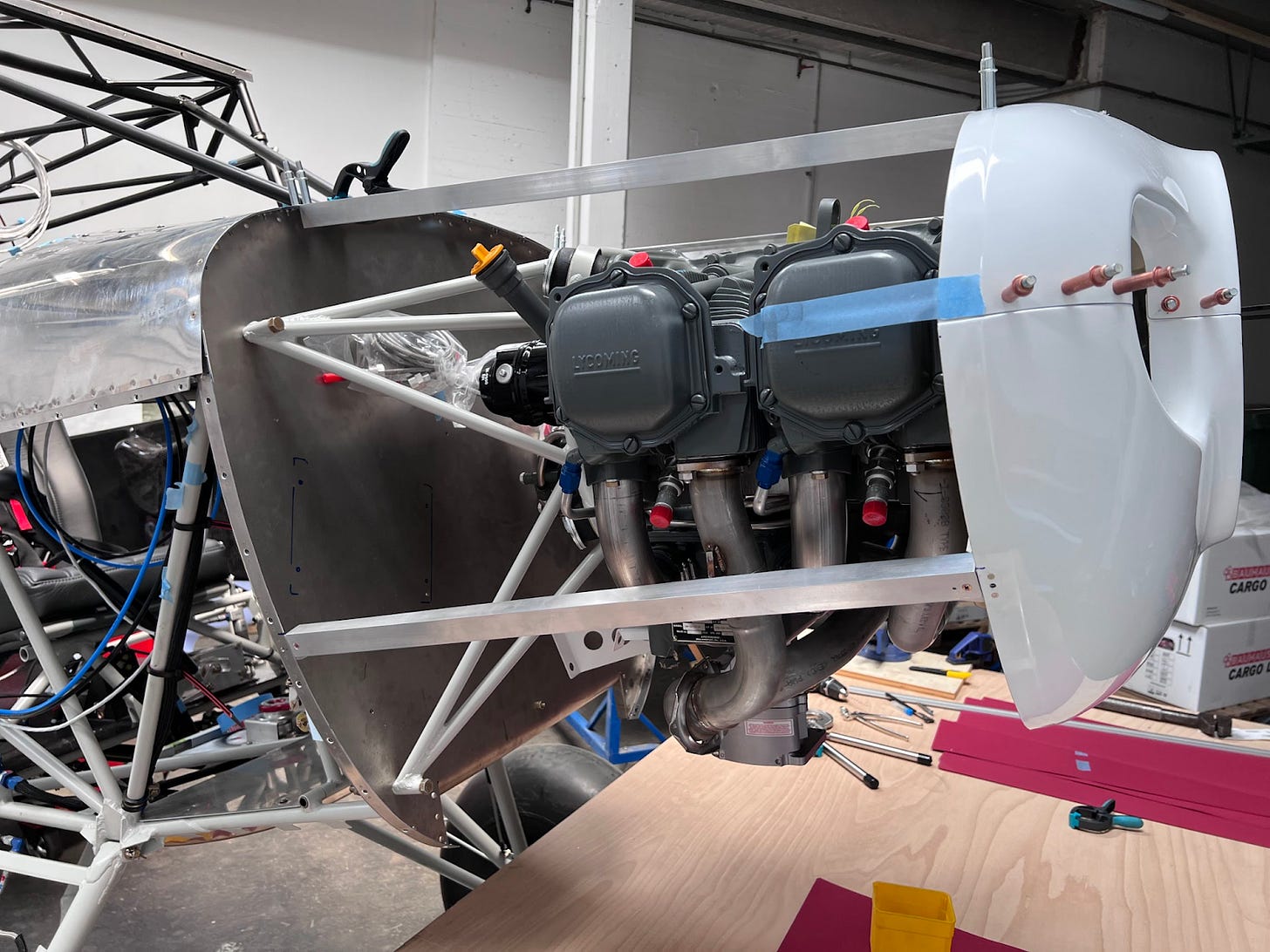
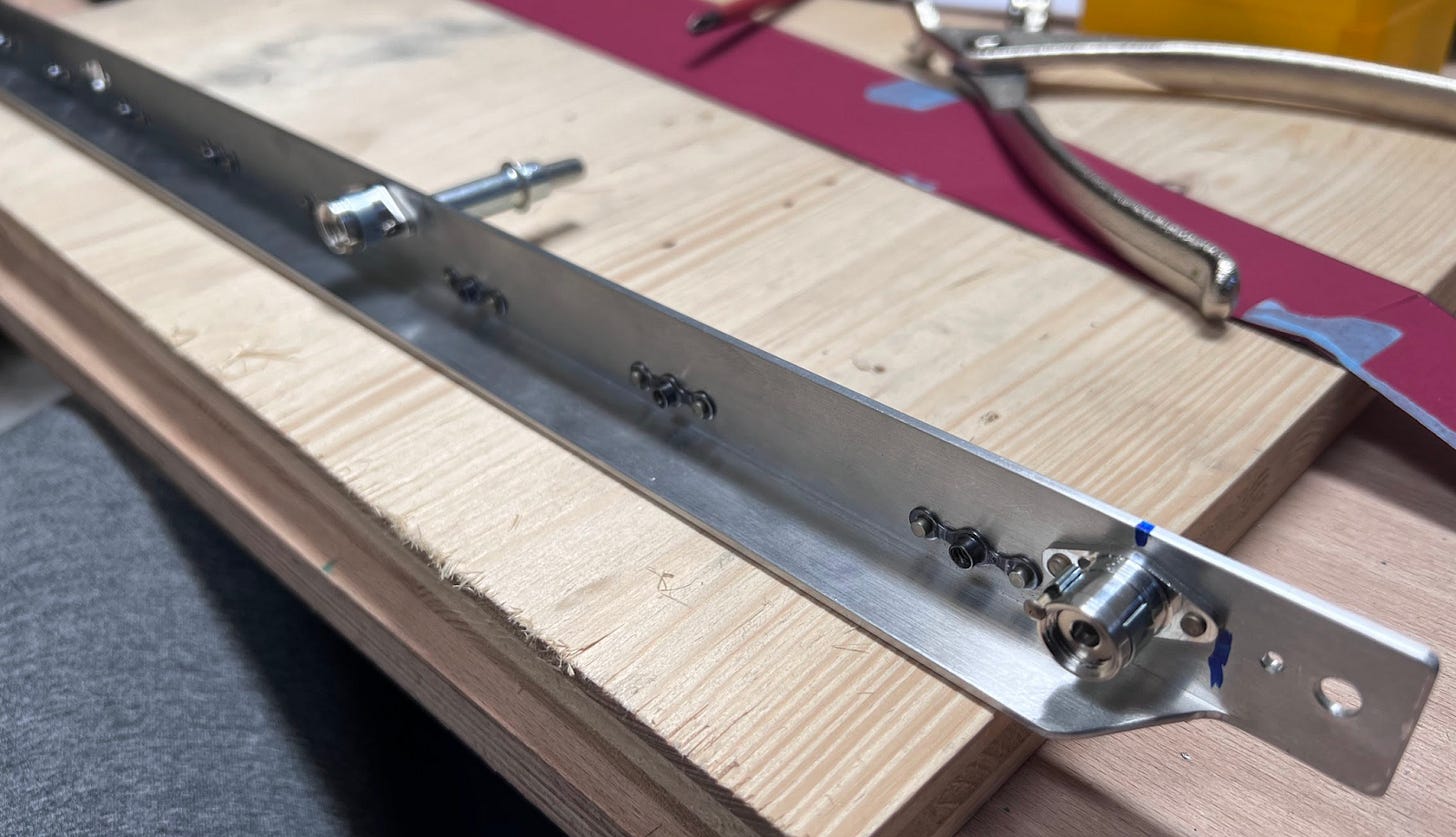
For structural support I used four aluminum extrusions. They run from the nose bowl to the firewall and determine the opening for the inspection doors. The door hinges attach to the top extrusions and the Skybolt (or Camloc or Dzus) fasteners are installed in the bottom one.
Making all parts removable takes a bit of tinkering. It is basically a matter of using nutplates and screws in the right places. Many screws have to be flush for this to work well.
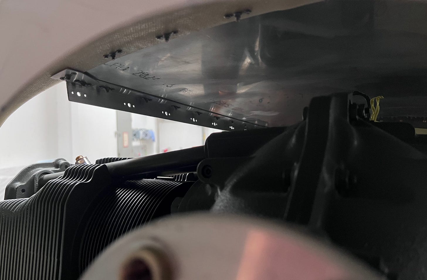
The top extrusions are fairly easy to install. The bottom ones need a fairly aggressive twist to align well with the rest of the skin.
To avoid having the crankshaft turn on me without noticing and ending up with a rotated nose bowl I strategically place some blue tape.
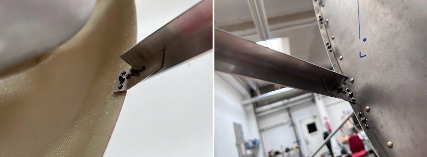
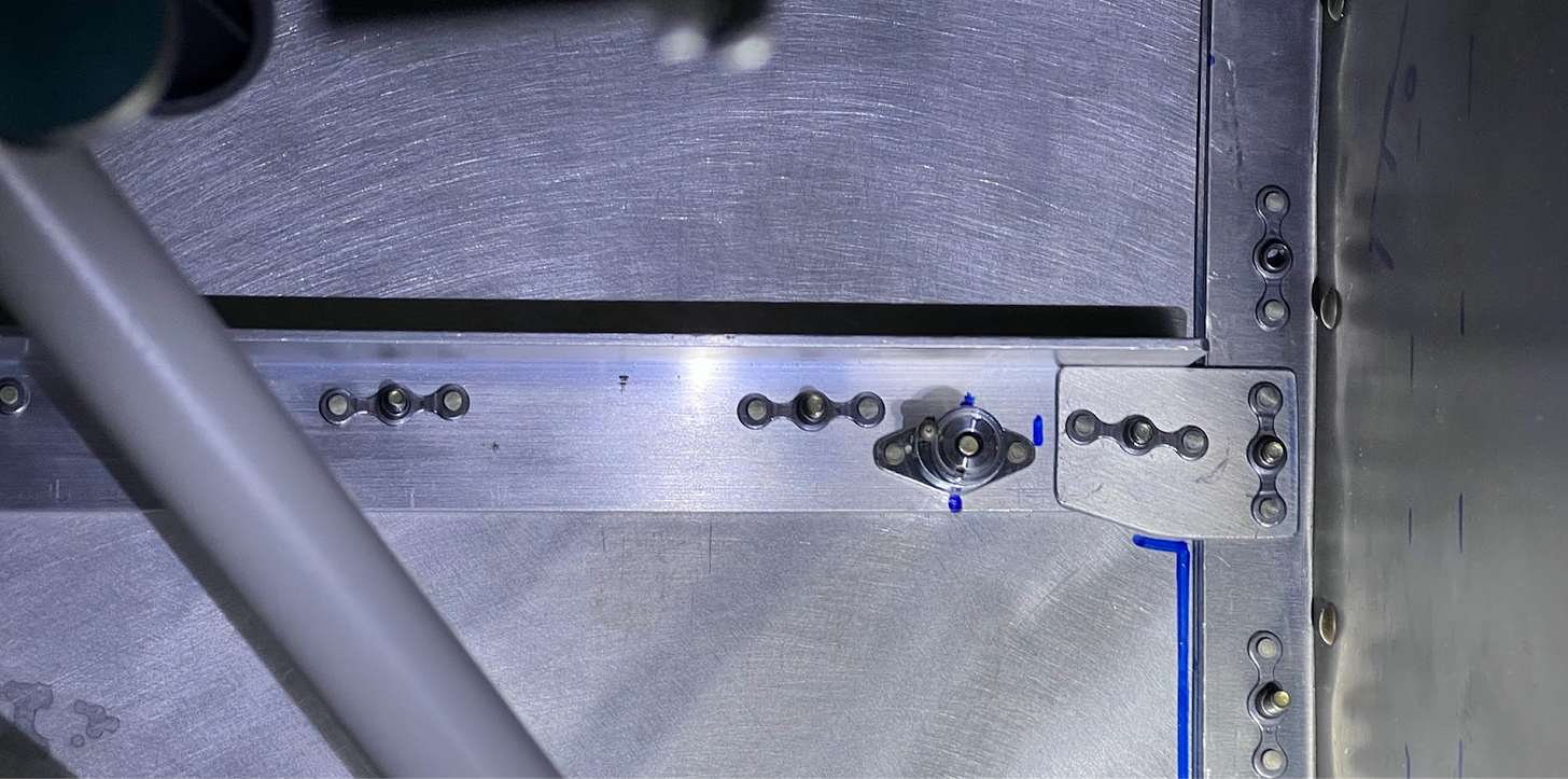
The extrusions are mounted with little backplates. I later had to shorten them to allow the Skybolt fasteners to be installed as close to the corner of the door as possible.
Top and Bottom Cowl
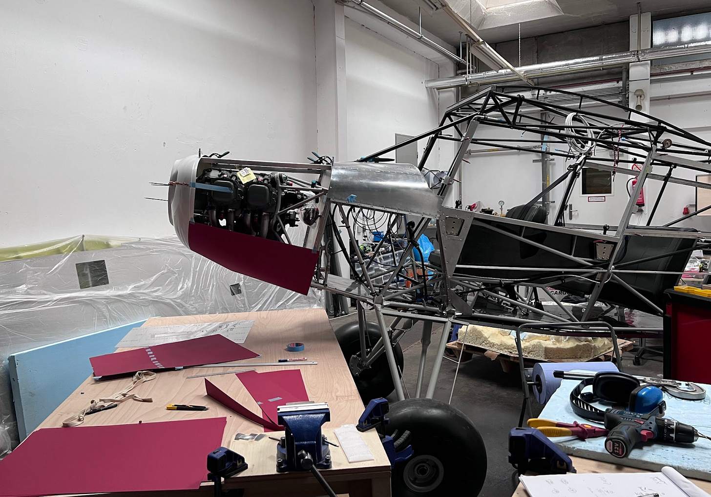
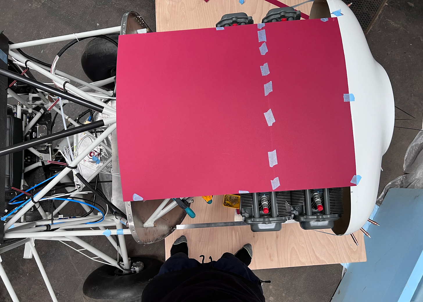
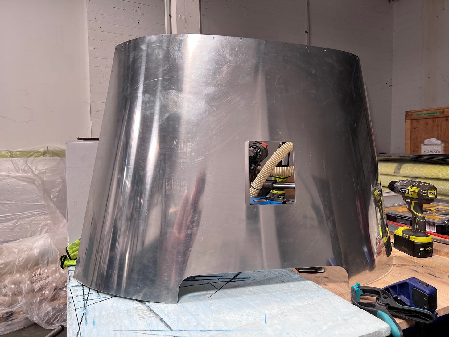
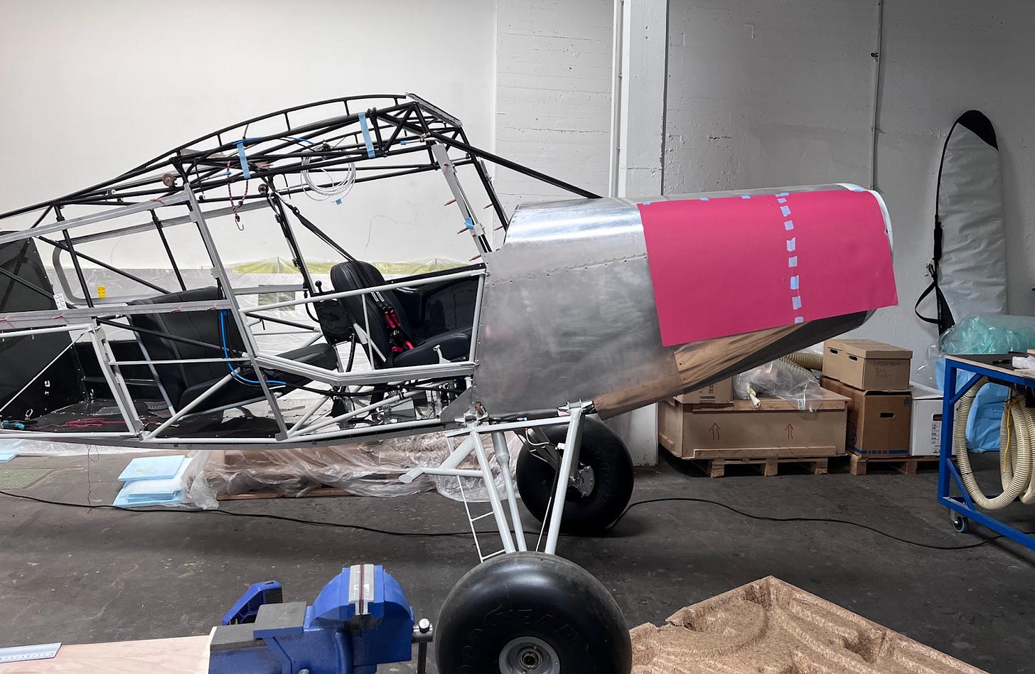
The cardboard aided design (CAD) method worked well to figure out the exact shape. Some important choices have to be made where all the mounting screws go. The corner areas are the crucial ones.
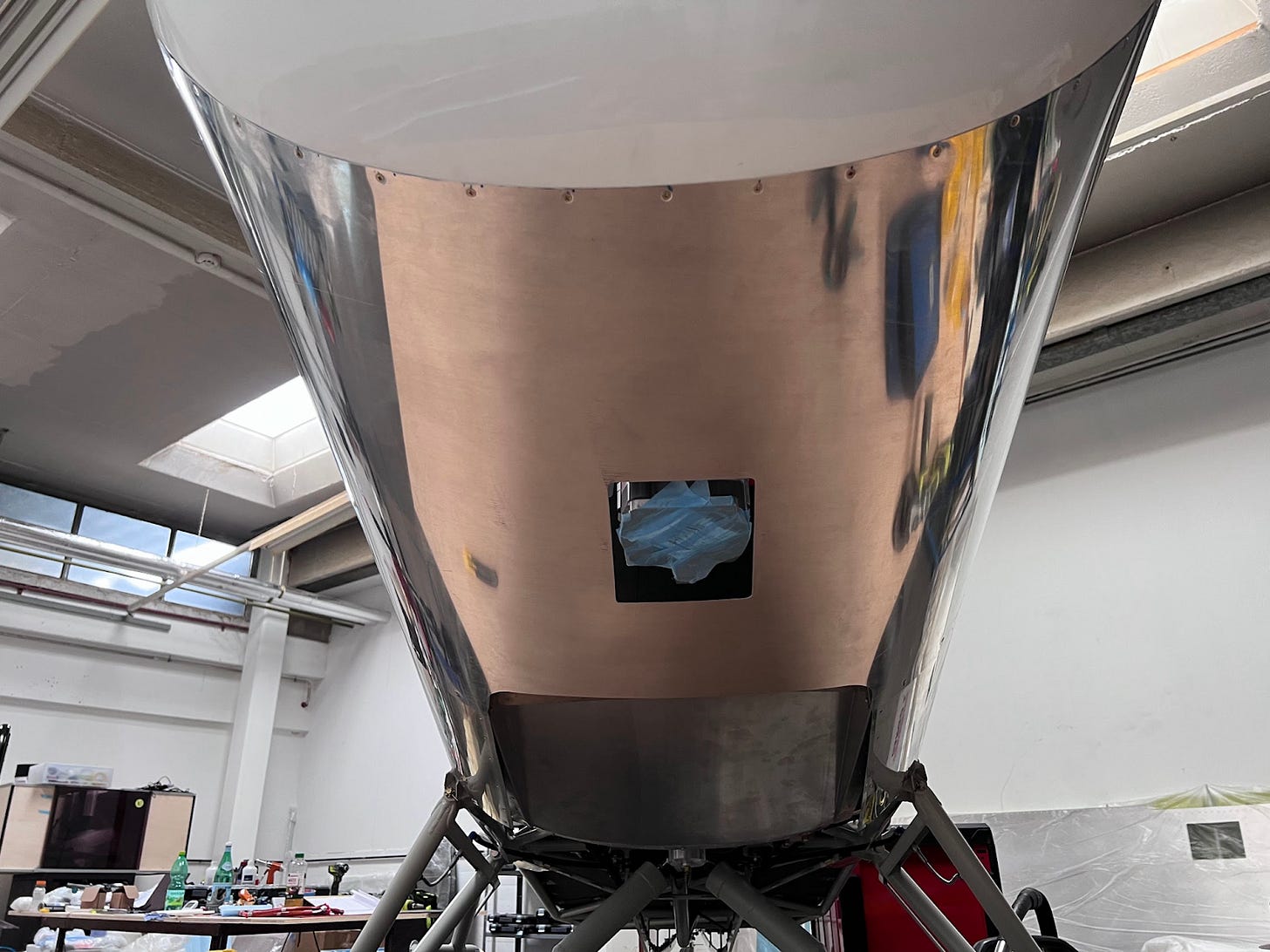
The bottom skin is more difficult to template. The curvature at the bottom determines the size of the piece. I decided to have it flatten out towards the tunnel without creasing it too hard at the ends of the firewall flange.
The bottom skin has two features, one for the carburetor air inlet and one for the tunnel exit. The inlet hole is minimal for now and the precise dimensions are to be determined later. The tunnel exit is a function of the inlet and outlet cross-section ratio. As a rule of thumb the outlet area should be 125% to 150% bigger than the inlet area. Also the exhaust pipes need to be able to comfortably protrude outside.
Notice how the flush screws along the firewall flange connect three layers of sheet metal to a nutplate. Also the nutplates of the boot cowl alternate with the ones of the cowl. All of them are size #6.
Cowl Doors
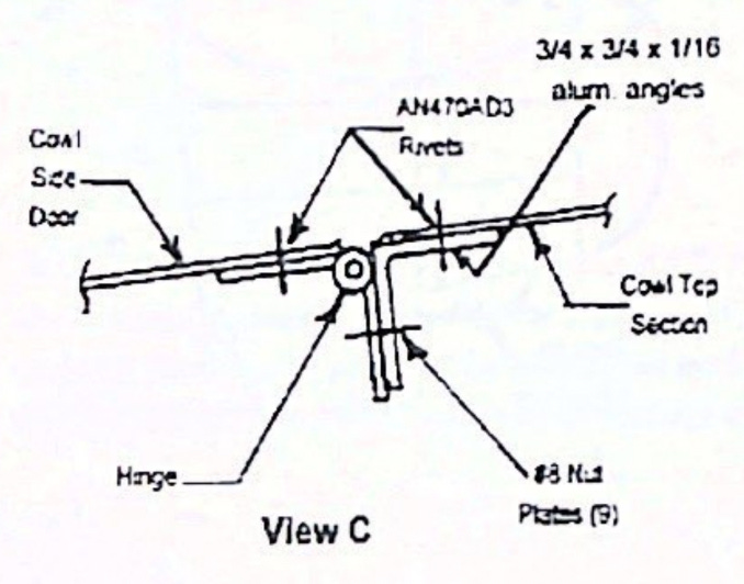
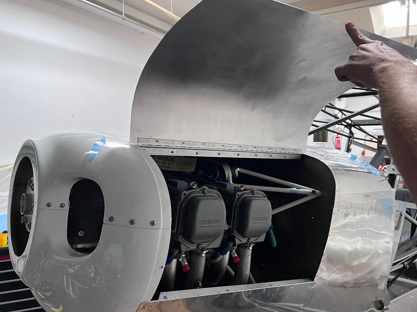
The Bearhawk Patrol Booklet has some good information on the cowl doors. The top edge is attached to MS20001P4 piano hinges. One tradoff is to mount them vertically on the aluminum extrusion. This creates a smooth installation but also limits how far the doors can be opened. They open enough to provide ample access but you won't be able to flip them onto the hood and have them stay open by themselves.
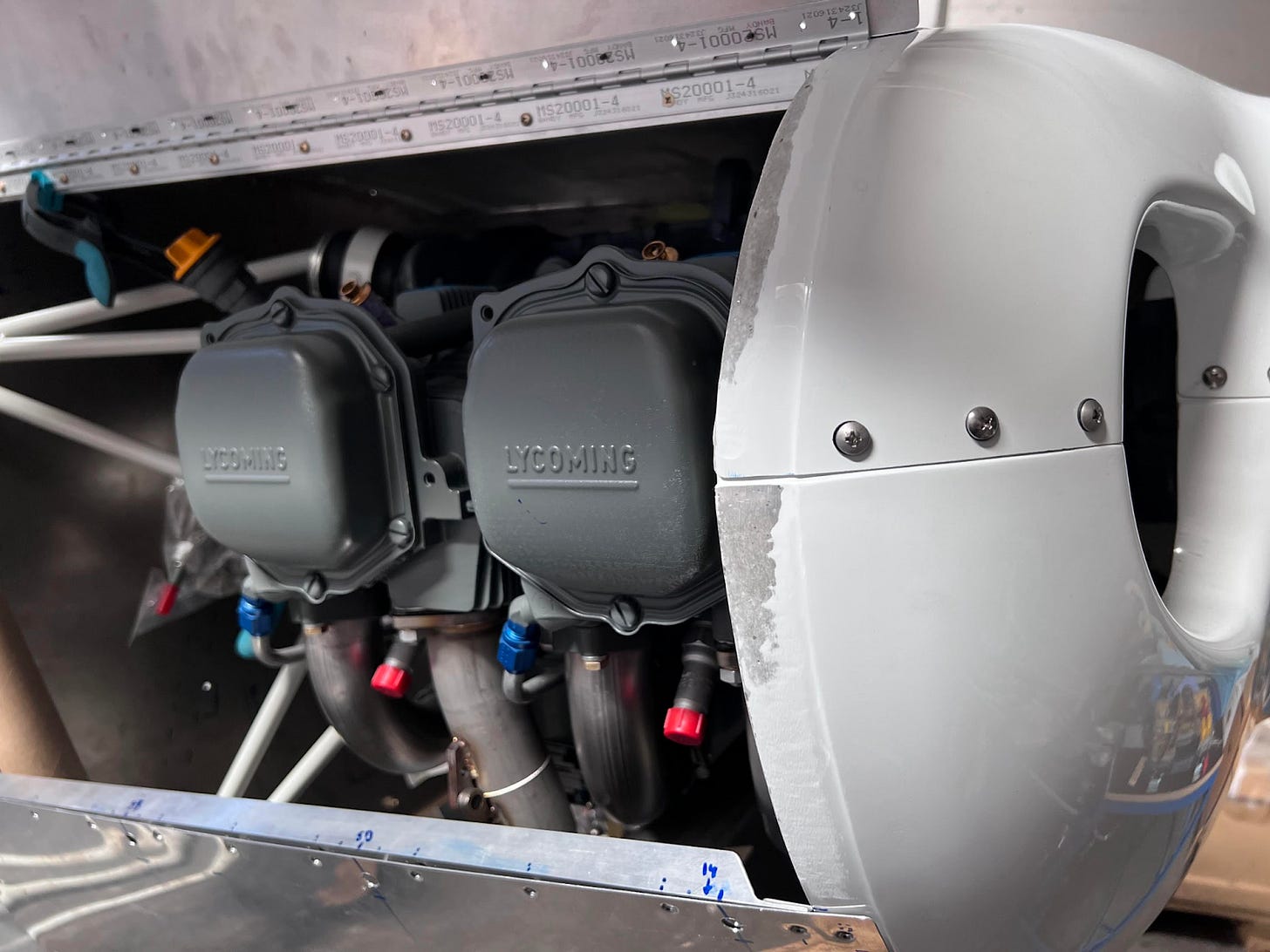
This is how I installed them with the option to remove the entire doors by simply removing a couple of screws. The hinges are attached with nutplates.
Here you can see how all these parts are nutplated together and can quickly be taken apart for maintenance.
This is how far the doors open with this hinge placement. I made sure the endstop is the hinge onto the extrusion and without any punctual sheet metal contact points.
Before installing the quick-release fasteners I am trying to shape the doors to match the curvature as best as possible. In the aft section this is a matter of tuning the curvature and in the front section I sanded the nose bowl to allow for easier matching. Generally speaking the nose bowl does not have a great flange to allow for a completely gapless transition. This may require some modeling and reshaping of the nose bowl to make it perfect. In retrospect the right thing to do would have been to modify the flange (doubling up on the inside, extensive sanding on the outside). This would have been better because all modding would be on the no-visible part.
In any case the door needs to be as tightly closed as possible before pilot-drilling the quick-release fastener holes.
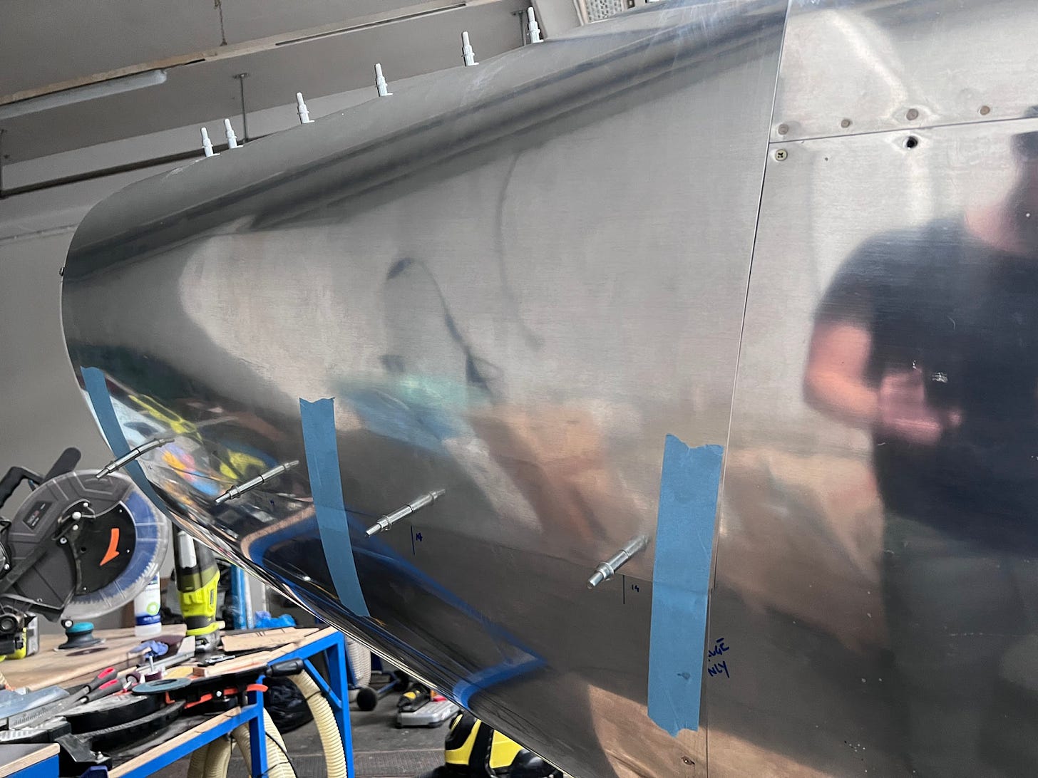
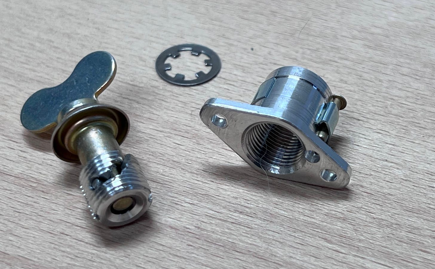
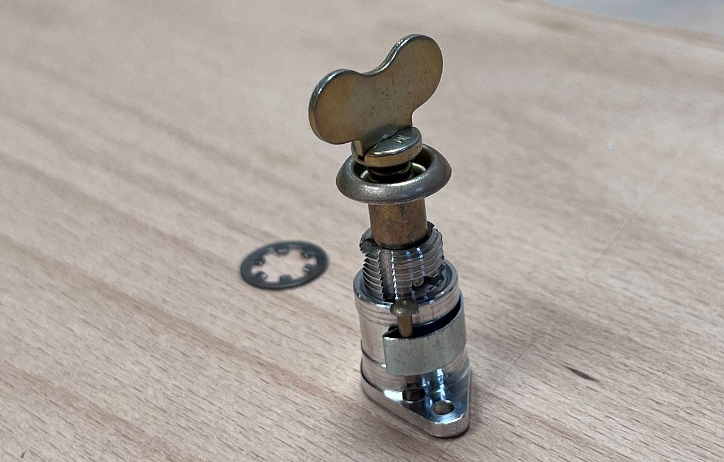
The main quick-release fastener options are Camlocs, Dzus and Skybolts. XHawk uses Skybolt 2600 series fasteners (SK2600-2W, SK2600-LWS, SK213-2). ACS carries them, they are competitively priced and they are adjustable. The adjustment feature is glorious.
The way this works is you simply install them, turn the fastener all the way tight, then thread it out about 1.5 rotations and pull the pin on the back. This locks the threading mechanism in place. With the right tool they can even be re-adjusted later.
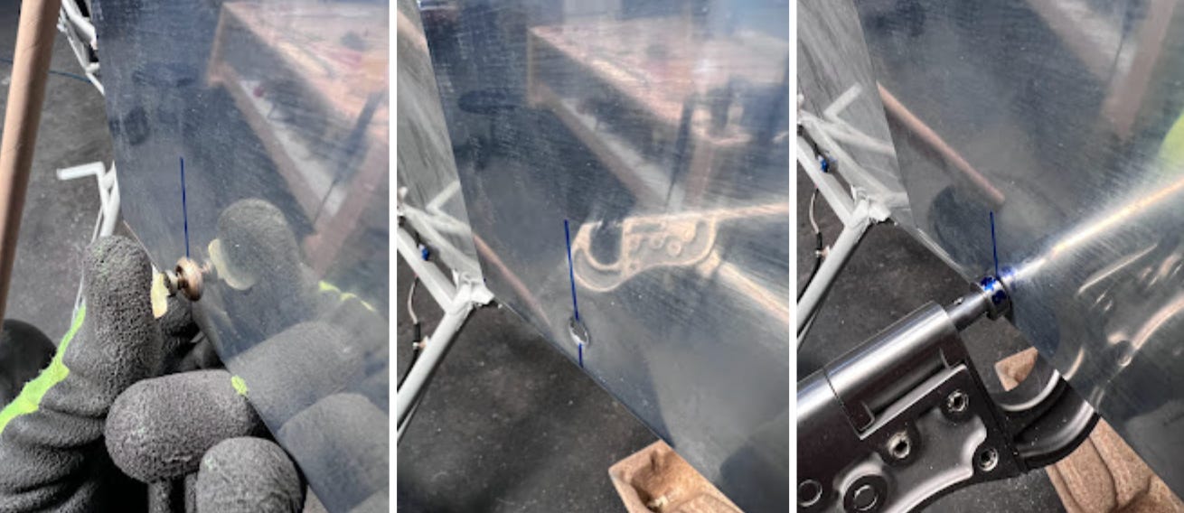
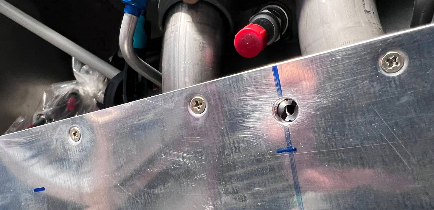
Take note that a 1/4" hole does not allow them to sit flush. I solved this by lightly dimpling the hole with a #8 dimple die. The hole on the layer underneath is bigger providing enough space for the dimpled door.
The convenience of removable parts allows, for example, installing the Skybolts on the bench.
Having the cowl doors in place is quite satisfying. It's a welcome booster in confidence that this will become a flying machine.
Air Intake
The details about heat box, carb heat, and filter are in the air intake post.

