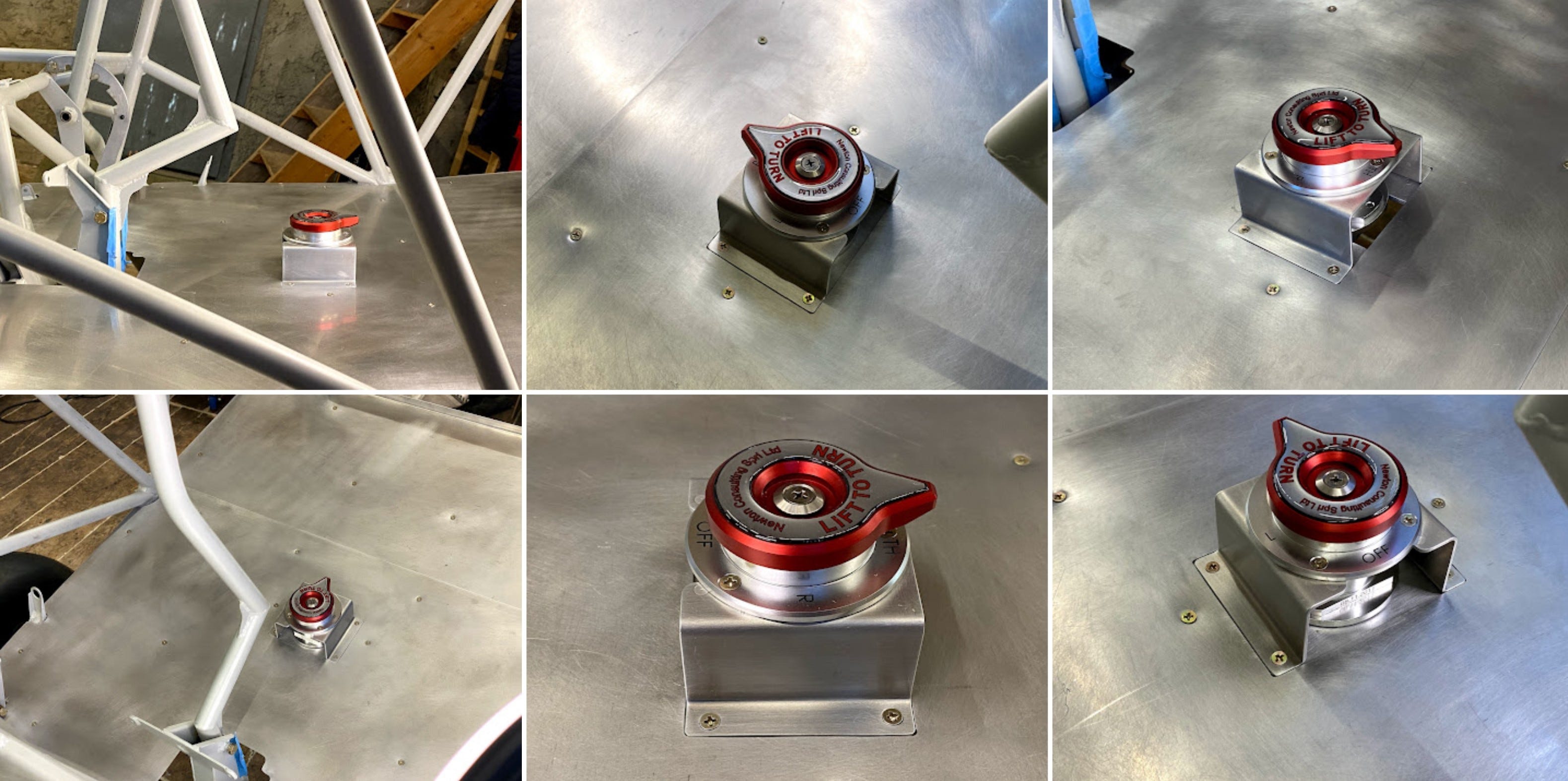
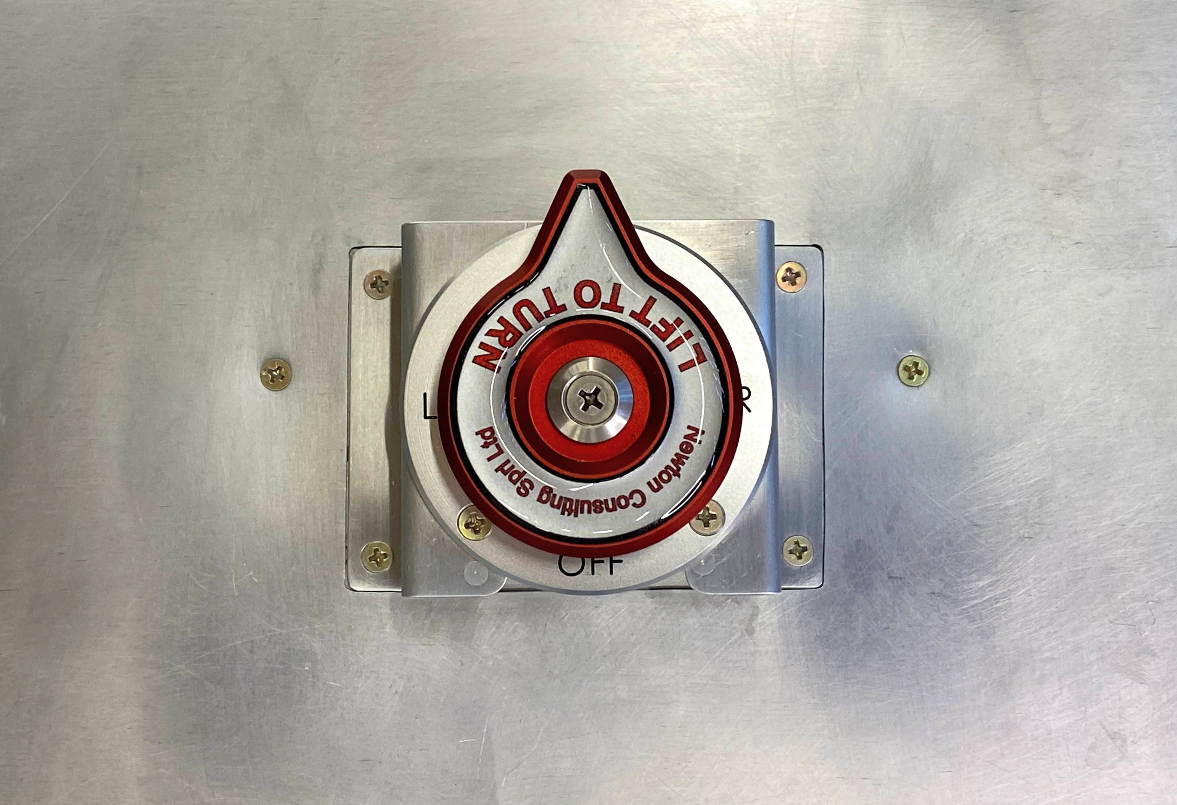
Fuel Selector Valve
Mounting the valve and gascolator unit.

The fuel system has two fuel lines running from each wing root to a T-fitting at the lower sides of the fuselage. From there one line on either side continues to the fuel selector valve.
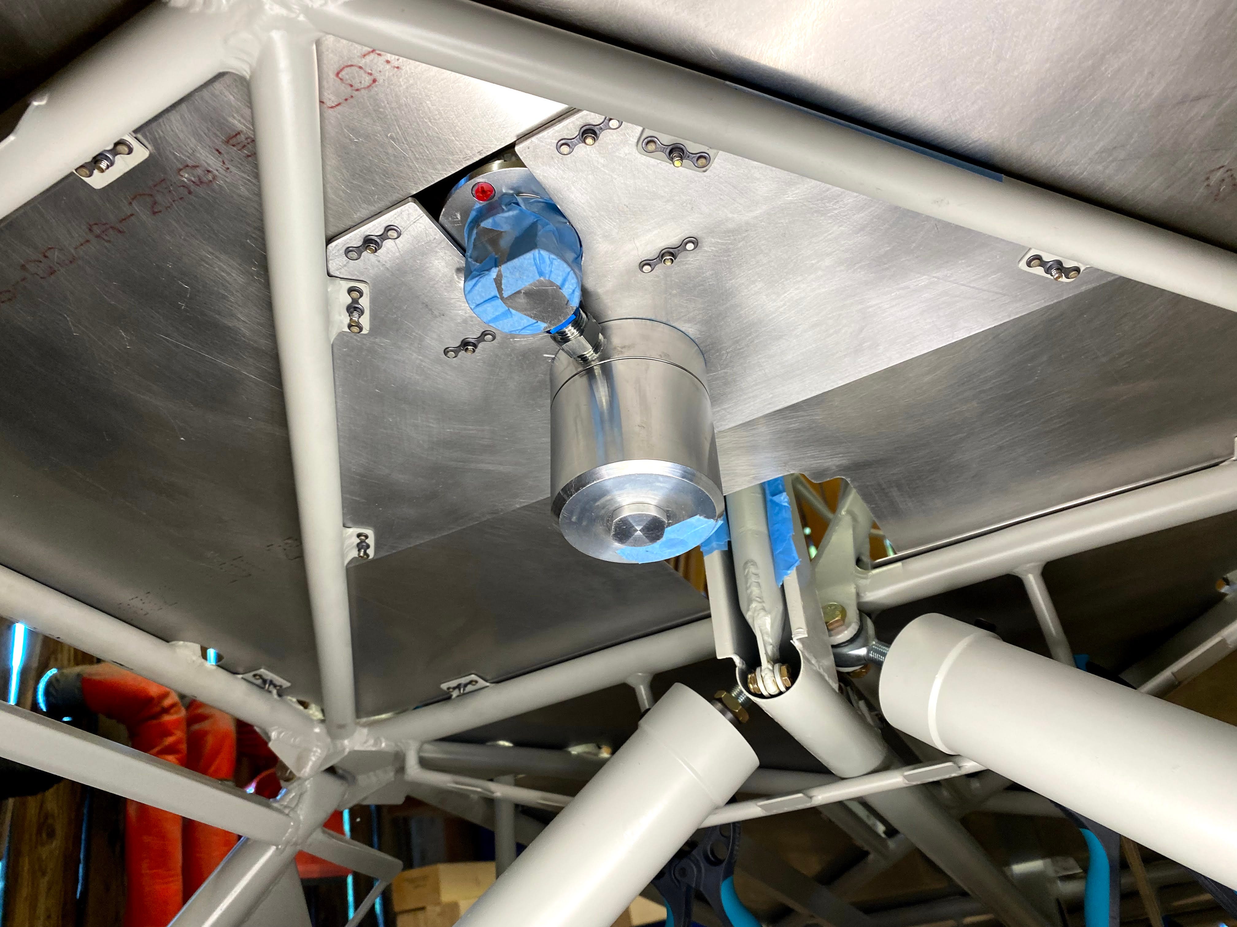
The fuel selector valve is coupled with the gascolator on its single output. This unit is mounted to a heavy duty aluminum mounting plate just underneath the floor panel. To mount this unit the valve and gascolator first need to be coupled.
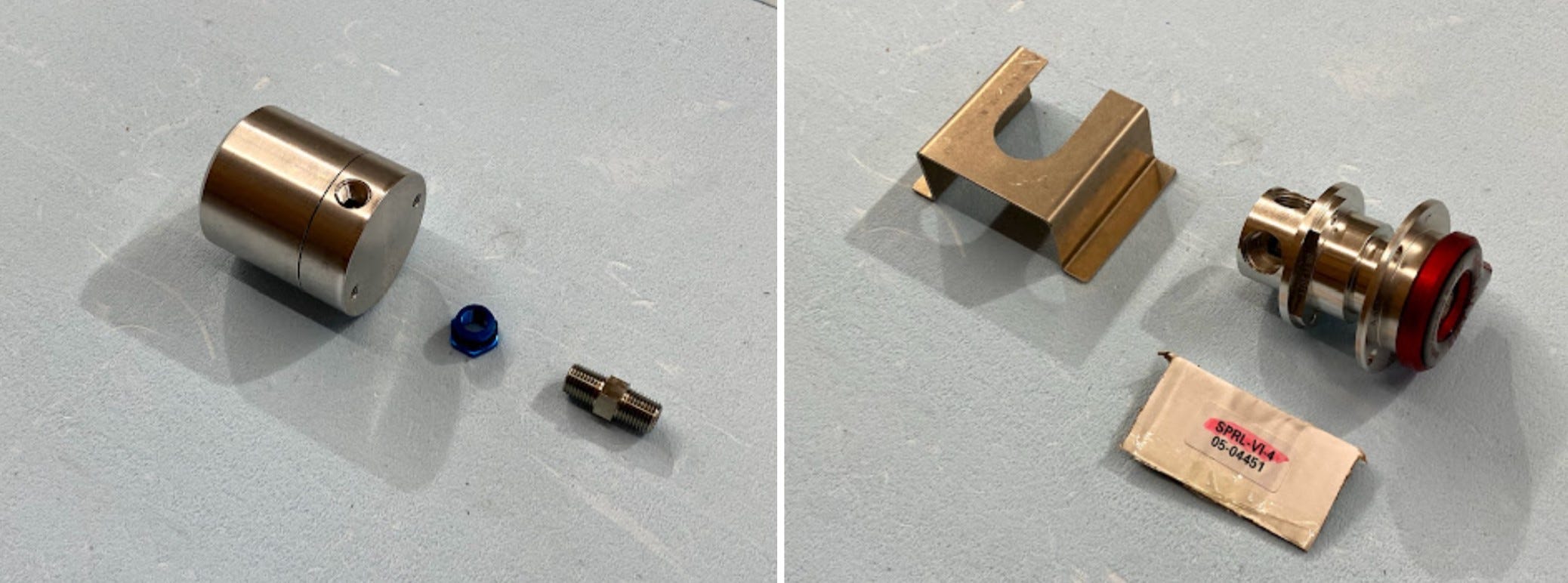
The blue anodized aluminum adapter fittings seal towards the valve with an O-ring. The NPT side (1/4”) requires a sealant. In principle NPT fittings can be sealed by lubricating (EZ Turn) and heavy torqueing. More reliably, according to a quick forum search is using some kind of anaerobic adhesive. The products in this field are quite vast and come optimized for different application (removable, potable, etc). They also typically need an activator on inactive metals (stainless, aluminum, cadmium) to speed up the curing time (metal ions cause the curing). For details there are brand-specific guides, for example the Loctite User Guide.
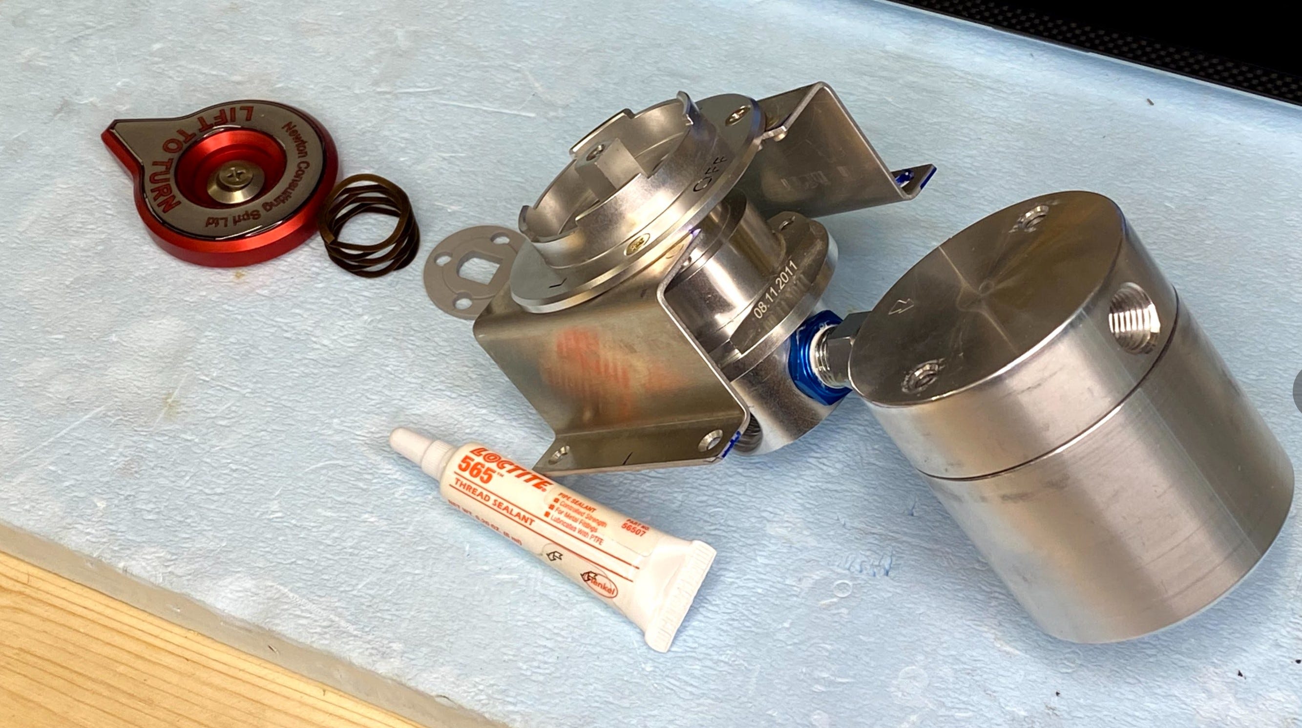
Once the units are coupled they can be match-drilled to the mounting plate. This involves a mounting bracket, 7x nutplates, and 2x 1/4-20 1/2” screws.
For details on the gascolator (torque values, maintenance) refer to the Gascolator Manual.
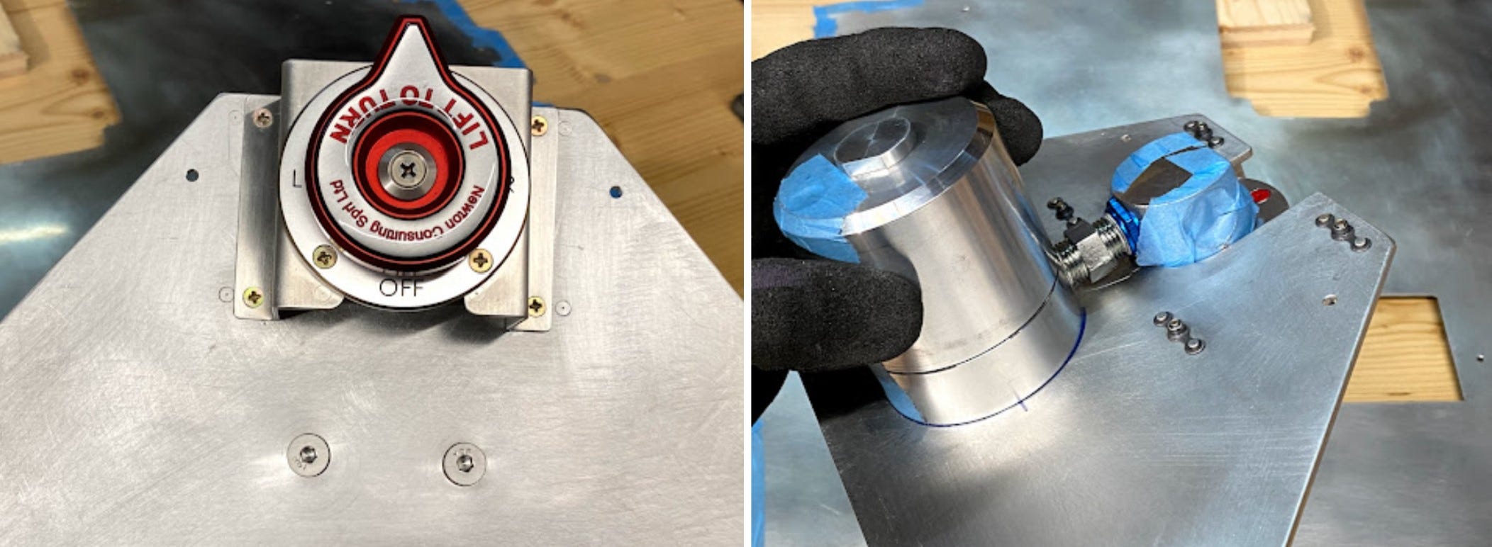
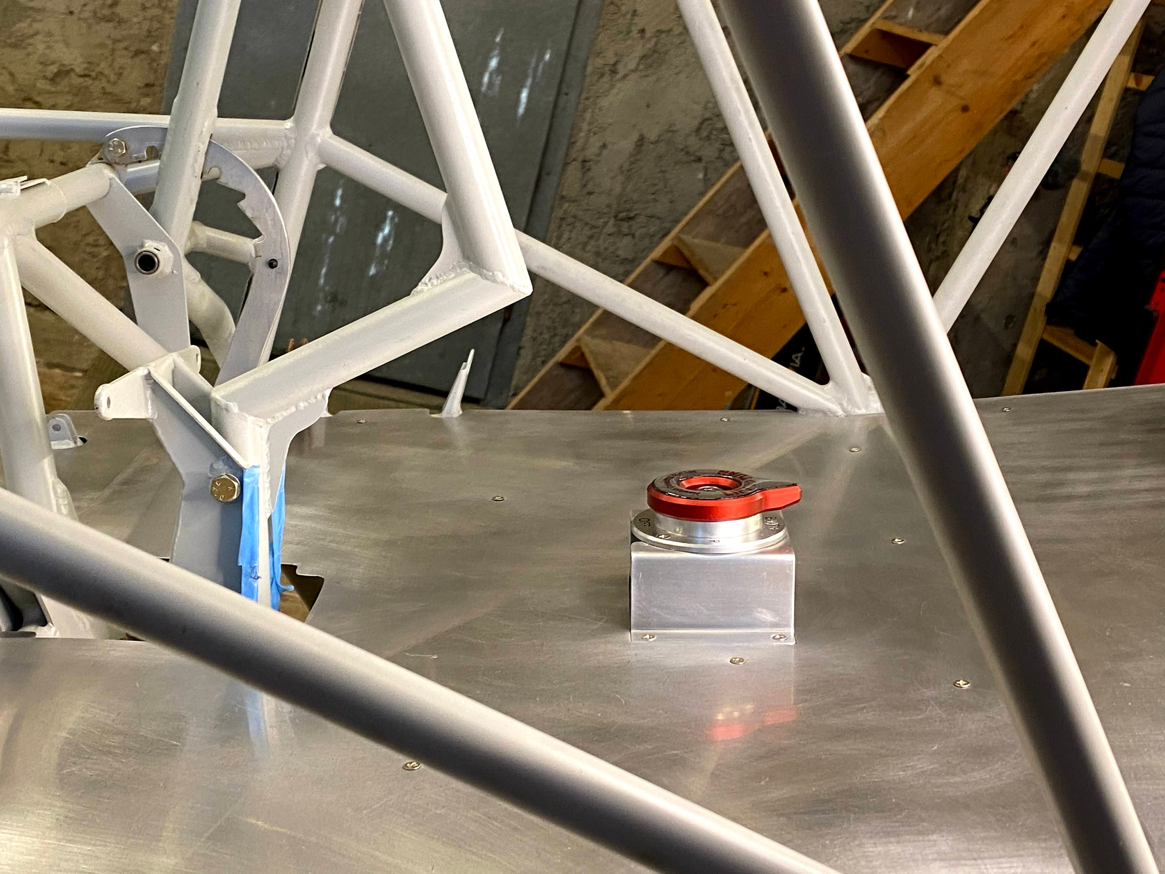
Finally the entire unit needs to be matched to the floor panel. For this I used a paper template to transfer the position. In tricky positioning tasks I try to get it as precise as possible with templates, then pilot drill, fix small positional errors with an end mill bit, then drill with final size.

All my floor panels are attached with countersunk screws (MS24693-S26) on dimpled panels and tabs with nutplates. This means the fuel selector valve mounting plate also needs to be countersunk and slightly longer screws (MS24693-S28 ) need to be used to mount in this area.